Digital
compass
|
(Spring
naar Nederlandse
tekst) The compass shown here is based on the KMZ51 from Philips. Very good application notes on the IC can be found here. Some of the pictures shown are from these notes. This IC consists of three elements:
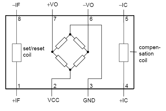 The
KMZ51 suffers from
a few artefacts. The
magneto-resistive materials are very much temperature dependent, noisy
and can have a big varying offset. By using the compensation technique
these problems can be accounted for.
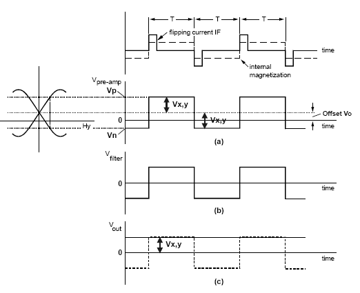
The measurement procedure is as follows:
From
the two
measurements the offset off the sensor and the
magnetic field can be calculated. For a measurement in all directions
two sensors need to be used. If the compensation method is used the
temperature dependence of the wheatstone bridge is accounted for as
well.
|
 |
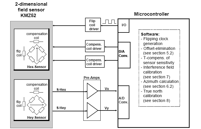
| The signals from the wheatstone bridge are amplificated by the rail to rail op amp and then measured by the microcontroller (AVR Mega8) AD converters. The compensation signal is generated by the PWM outputs of the microcontroller. The flipping pulses are generated by pulsing two microcontroller digital outputs and then amplificated by the Darlington transistors. |
 |
The following electronic design is used: |
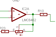 |
| The
sensitivity of the design can be altered by changing the amplification
of the opamps and by changing the compensation coil's serial resistors.
|
|
Deze tekst is grotendeels automatisch vertaald uit het Engels, vandaar de soms wat kunstmatig aandoende teksten. De ergste missers heb ik eruit gehaald. Het kompas is gebaseerd op de KMZ51 van Philips. De zeer goede toepassingsnota's over IC kunnen hier worden gevonden. Enkele figuren op deze pagina zijn van deze datasheets. Dit IC bestaat uit drie elementen: 1. Een brug van wheatstone die bestaat uit vier magneto-resistive weerstanden. Het (verschil)voltage op de brug is evenredig met het magnetische veld. 2. Een spoel: 'flipping coil', waarmee de metingsrichting van de sensor kan worden veranderd. 3. Een compensatiespoel. Met de stroom door deze spoel kan het magnetische veld worden gecompenseerd. De KMZ51 kent een paar artefacten. De magneto-resistive materialen zijn zeer temperatuur afhankelijk, geven veel ruis en hebben een forse varierende offset. Door de compensatietechniek te gebruiken kunnen deze problemen worden opgelost. De metingsprocedure is als volgt:
De signalen van de wheatstonebrug worden verstert door een rail to rail opamp en dan gemeten door de microcontroller (AVR Mega8) AD convertors. Het compensatiesignaal wordt geproduceerd door de PWM outputs van microcontroller. De stroom pulse door het 'flipping coil' wordt gemaakt door de microcontroller digitale output te pulseren en en dit signaal te versterken met Darlington transistoren. |