| These are the lates (06-02-06) results: | ||||||
|
||||||
|
|
||||||
|
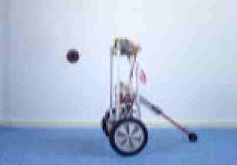
Balancing
robot
|
||||||
 (Spring
naar Nederlandse
tekst) (Spring
naar Nederlandse
tekst)Balancing a robot Building
a balancing robot has
become a holy grail for a lot of robot builders. Two very inspiring
examples are the nbot
of
David P. Anderson and Joe le
pendule made at L'Ecole
Polytechnique Fédérale de
Lausanne. Both sites contain nice movies.
The basic problem of balancing a robot on two wheels is first to get to know parameters like: -
the speed of the robot
- angle of the robot to the floor - the speed this angle changes When
controlling the robot these
parameters need to be combined and used to move the robot forward and
backward in a way it stays upright. This is the basic and VERY
challenging
control problem. Explore the WWW and you will find a lot of information
on the physics and mathematics of the problem.
The way I solved and worked out the problem is explained in the following sections. |
||||||
 Basic
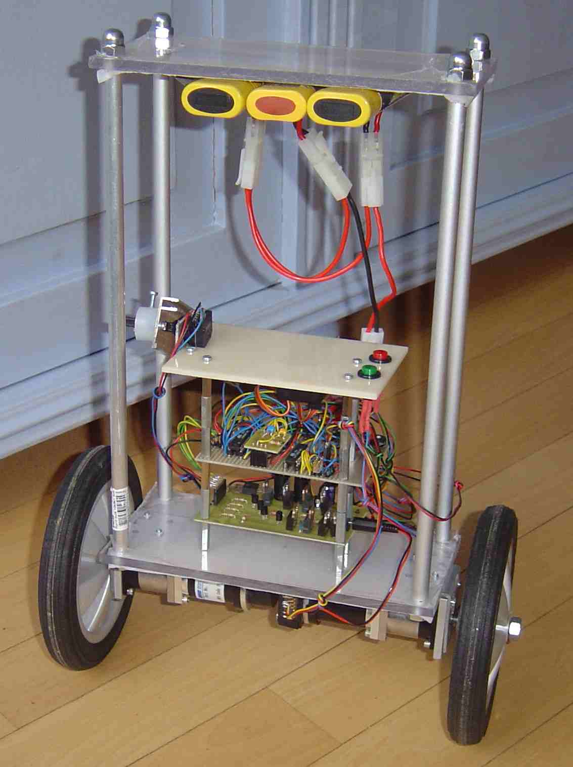
hardware Basic
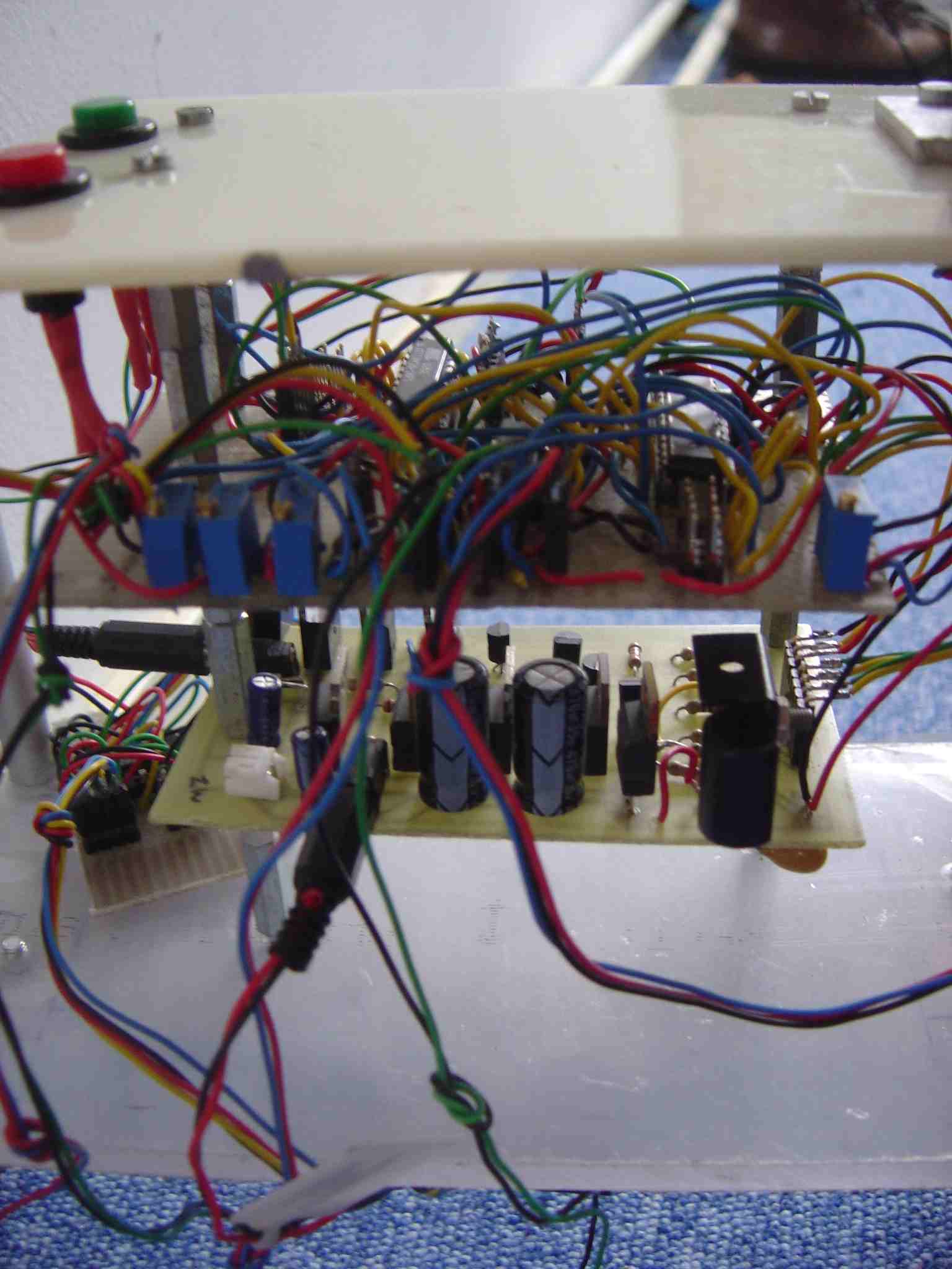
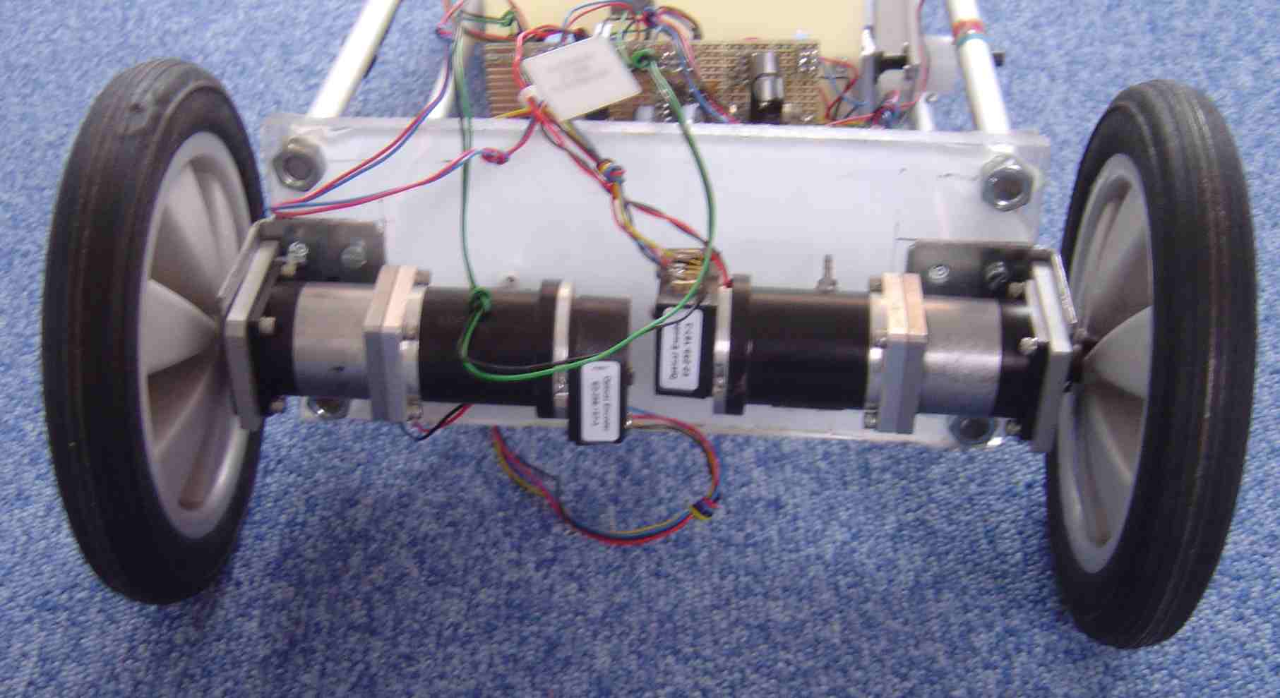
hardwareThe balancing robot shown uses: -
AVR Mega8
- AVR Tiny26 - 3x7.2V accupack - QMC motors with planetary transfer and decoders (no specifics known) - gyroscope - ADXL202 acceleration measurement IC (datasheet) - full H-bridge based on TIP41C en TIP42C transistors (schematics) |
||||||
This
is a schematic
overview of
the robot. |
||||||
| The
combination of the
different
modules
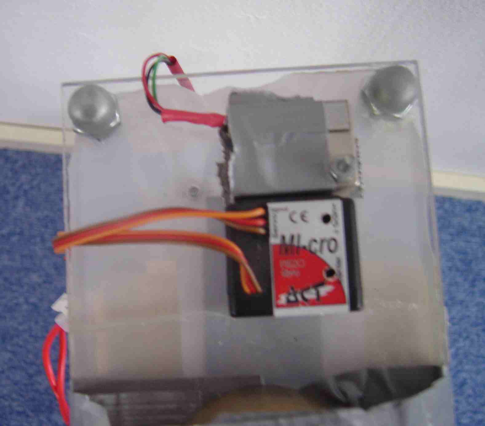
electronically is very straight forward. Both gyro and accelerometer
have digital outputs with pulse width modulation. No electronic signal
conditioning is necessary. If you need any
details for
use in your own projects you’re welcome to email. |
||||||
| Software The software is developed in BASCOM. This is a detail of the control (all in software). 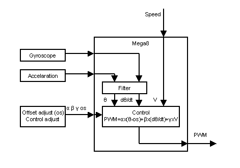 |
||||||
|
Measurements
 The
encoders give about 30.000
pulses per rotation. Speed
measurement is therefore done separately by a
Tiny26 to ensure stable timing on the Mega8. The control loop needs to
be run at a fixed time interval. No interrupts can be accepted. The
encoders
have a A and B output, which make the speed and direction measurements
simple. The
data is transferred serial to the Mega8.
Both
measurements are needed for
a few
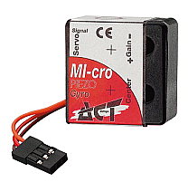
reasons:The acceleration measurement is done with a ADXL202. See the datasheet for more specifics. The connection of the IC is very simple. I use the digital output of the IC. The measurement of the angle speed is done with a gyroscope. I use a standard gyroscope used in model planes and helicopters. The angle speed measurement and the acceleration measurement are combined to determine the angle the robot makes with the floor.
|
||||||
| (Kalman)Filter A Kalman filter can be used to combine the gyroscopic measurements and the acceleration measurements. A lot of extensive (mathematical) explanation on this filter can be found on the WWW. The filter is applied by the program in the microcontroller. I used Mathlab to simulate the filter before implementing. After a lot of trials and calibration the performance of the Kalman filter was not satisfying. I developed another simple filter again on trial and error: 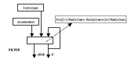 I am not aware of any theoretical basis of this filter. It is probably a reinvention of a existing filter. Suggestions are welcome. 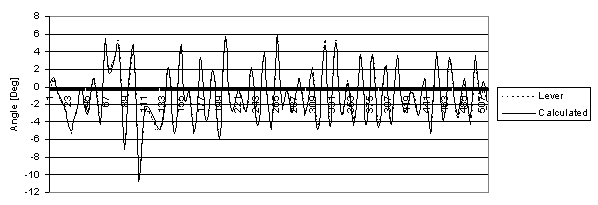 |
||||||
| Adjustment
of the control loop During
development it turned out that
it would be useful to be able to make fast and easy adjustments of the
control loop without having to reprogram the robot. Several
potentiometers were attached to +Vcc and GND
while the lever of the potmeters was attached to the ADC’s of
the
Mega8. When adjusting the potmeters the reading of the ADC’s
changes having a direct effect on the control loop (programmed to do
so).
This method is also useful for adjusting the zero point of the robot. When the robot has a ‘favourite’ direction to fall or drive to, this can be compensated by a (small) offset correction. |
||||||
| Control The
basic
control loop is very simple. Just
have a linear feedback from the speed, angle and angle speed to the
motors. Mind the signs of the feedback constants: positive for angle
and angle speed, negative for speed.
|
||||||
| Development A few things I learned during development: -
Start with a tall
robot that has a high centre of gravity.
These are more stable.
- Start with big motors. - Start with high accu voltages. - The adxl202 is very sensitive to interference. - Put the accelerometer and the gyro close to each other on your robot. |
||||||
A pitfall can be the behaviour of the motors. Normally some kind of linear behaviour is assumed. This is the measured PWM-N curve of my motors (PWM=setting of the 10 bit PWM output, N=measure of the speed of the motors).  As you can see there are three distinctive zones in the characteristics. My interpretation is as follows:
|
||||||
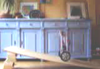
| Completing
the whole robot
at once
(like I did first) is not very smart. Start with developing the control
loop.
You can do this (e.g.) by attaching a lever (an arm) to the robot.
Connect
this arm to a potmeter that can be read by the processor (ADC). With
this
flexible arm you can read the angle the robot makes with the floor.
Then you have a
direct measure of the angle and angle speed of the robot (if you do the
math). This movie
shows my robot with just the lever/arm. Adjusting the constants in the
control loop might cost you some time then. |
||||||
|
15-01-06 The robot will not function better with gyro and acceleration then it ever did with a lever or arm attached. So the control loop was further improved using the arm. When the arm is removed the robot will benefit from the improved control loop. These are the improved results. |
||||||
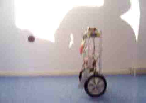
Develop the gyro and acceleration measurement separate from the control loop. Tuning the constants used in the filter is a must and might cost again some nights!!!! The lever that is still attached to your robot remains very handy when calibrating the filter. When your are confident in both the filter and control loop you can combine them and remove the lever. This movie shows my robot without the lever/arm, just on the gyro and accelerometer. It's reasonable stable. Pushing the robot makes it swing but not fall (yet). Pushing the robot makes it push back, a very funny experience. |
||||||
| See
my
links section for
more
background information on the several topics. |
||||||
|
||||||
Een
balancerende robot
Het maken van een balancerende robot is voor een groot aantal robotbouwers een soort heilige graal. Twee inspirerende voorbeelden van goedwerkende balancerende robots zijn de nbot van David P. Anderson en Joe le pendule gemaakt op de L'Ecole Polytechnique Fédérale de Lausanne. Op beide sites zijn leuke filmpjes van de robots te bekijken. Om een robot op twee wielen te laten balanceren is het noodzakelijk de volgende parameters te bepalen:
De manier waarop ik de sturing heb uitgewerkt staat beschreven in op deze webpagina. Het combineren van de verschillende modules (zie figuurtjes in de Engelse text) is vrij recht toe recht aan. Zowel de gyroscoop als de versnellingsopnemer hebben digitale uitgangen met puls breedte modulatie. Deze signalen kunnen direct ingelezen worden (hoeven niet te worden versterkt o.i.d.). De software is geschreven in BASCOM. De metingen De encoders op de motoren geven ongeveer 30.000 pulsen per omwenteling. Daarom worden de snelheidsmetingen door een afzonderlijke Tiny26 uitgevoerd zodat de timing op de Mega8 stabiel blijft. De besturingsloop op de Mega8 moet draaien met een vast tijdinterval. In deze loop kunnen geen interrupts worden geaccepteerd. De richting van de wielen kan worden bepaald omdat de encoders een A en een B uitgang hebben. De data wordt van de Tiny26 naar de Mega8 gestuurd. De versnellingsopnemer wordt uitgevoerd met een ADXL202 (zie datasheet). Ik gebruik de digitale uitgang van dit IC (puls breedte modulatie). De meting van de hoeksnelheid wordt uitgevoerd met een gyroscoop (modelbouw, via Conrad). De versnellingsmeting en de hoeksnelheidsmeting worden gecombineerd om de hoek te bepalen die de robot maakt met de vloer. Beide metingen zijn noodzakelijk:
(Kalman)Filter Het zogenaamde Kalmanfilter kan worden gebruikt om de gyroscoop- en de versnellingsmeting te combineren. Er is veel (wiskundige) achtergrond over dit filter te vinden op het WWW. Het filter wordt toegepast middels berekeningen van de microcontroller. Ik heb Matlab gebruikt om de werking van het filter te simuleren voor implementatie. Na veel testjes en calibratiemetingen bleek het Kalman filter echter niet te voldoen. Op basis van trial en error heb ik een alternatief filter ontwikkeld (zie figuren Engelse sectie). Instellen van de besturing Het bleek erg handig om snel de besturingsloop te kunnen aanpassen zonder de microcontroller te herprogrammeren. Dit is gerealiseerd door verscheidene potmeters tussen +Vcc en GND aan te sluiten. De loper van de potmeters zijn aangesloten op de ADC's van de microcontroller. Door de potmeters in te stellen wordt via het microcontrollerprogramma de besturingsloop direct aangepast. Deze methode kan ook gebruikt worden voor regelen van een nulpunt. Als de robot een favoriete richting heeft om naar toe te vallen dan kan dat worden gecompenseerd door een kleine offset correctie toe te passen op de gemeten/berekende hoek van de robot. Besturing De besturingsloop is eenvoudig. Het is een lineare terugkoppeling van de snelheid, hoek en hoeksnelheid van de robot op de motoren met de volgende tekens: positief voor de hoek en hoeksnelheid en negatief voor de snelheid. Ontwikkeling Houdt rekening met de volgende valkuilen:
Na de besturingsloop kan de gyro- en versnellingsmeting uitgewerkt worden. Het signaal van de potmeter bevestigt aan het armpje dient daarbij als referentie/calibratiesignaal. Het tunen van de constantes gebruikt in het filter kan opnieuw wat tijd vergen. Nadat zowel de besturingsloop als de gyroscoop/versnellingsmeting/filter geoptimaliseerd zijn kunnen deze gecombineerd worden en kan het armpje verwijdert worden. Zie mijn links pagina voor meer filmpjes, robots en achtergrond over balancerende robots. |